![]()
![]()
3D Model Course Designing with 3dStudio Max
Tutorial 4
![]()
Step 9: Creating line textured objects.
Border and line textured objects are used for footpaths, green fringes, bunker fringes etc ...
The method is very similar to that used for area objects. The only differences are the rendering settings and that the objects are not Extruded.
OK. Let's make a footpath.
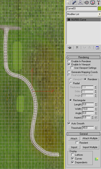
Step 1. As with area objects, select the Shapes Tab in the top right hand menu.
Step 2. Open the combo box and select NURBS Curves.
Step 3. Select the Point Curve button.
Step 4. Click points along the footpath in the background image in the Top viewport. When you have reached the end of the footpath, right mouse click to end the point entries.
Step 7. Select the Modify Tab and - in the Rendering rollout - select Enable in Viewport.
Step 8. Select the Rectangular option radio button and set the length to 0 and the width to an appropriate value. This value determines the width of the footpath so experiment with this value until it matches the footpath width in the background course hole template image. You should immediately see the results in the viewport.
Step 9. Convert to Editable Mesh and remove the back faces as described earlier.
Step 10. Apply the texture as you did with the green using a suitable footpath texture.
Step 11. If you would like to add a fringe then we need to draw lines on both sides of the footpath.
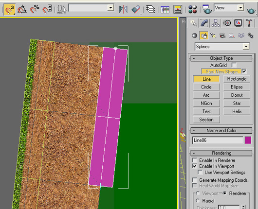
Use the Line Spline and activate the "Magnet 3" Snaps button. (here shown on top left of screen shot).
The snaps mode will guide you along the edge of the footpath by showing a blue cross cursor when a vertex point is near. Just click every time the blue cross appears as you move along the edge of the footpath.
Set the rendering width to 2 and length to 0..
Step 12. Convert to Editable Mesh when the line is completed. (Do not remove backfaces for fringes.)
Add the texture as described in the next Step (Step 10.)
Here the footpath complete with fringe.
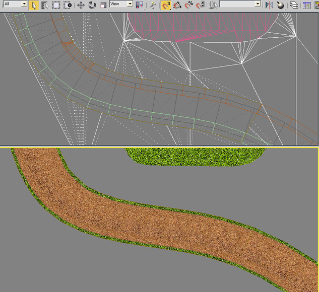
Once the footpath is completed we need to make a cutout for the surrounding surface.
In order to do this we need to draw a complete closed spline line around the path and fringe. But because the object is usually quit long, it's quite difficult to do this without panning. Panning the view to get the next segment into view while drawing the line can be awkward so it's probably better to do this in segments. ie drawing closed splines around smaller (in view) segments of the footpath and then moving (panning) to the next segment to draw another closed spline. You can then create the compound objects for the cutouts in the usual manor for each footpath segment.
Activate the "Magnet 3" Snaps button while drawing the closed spline line around each segment.
Step 10: Texture Mapping the fringe.
Your object fringe will likely have a surface transition as with sand bunkers with a rough/sand transition. If you have a suitable texture bitmap then this can be mapped to the fringe.
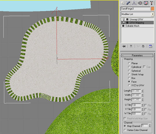
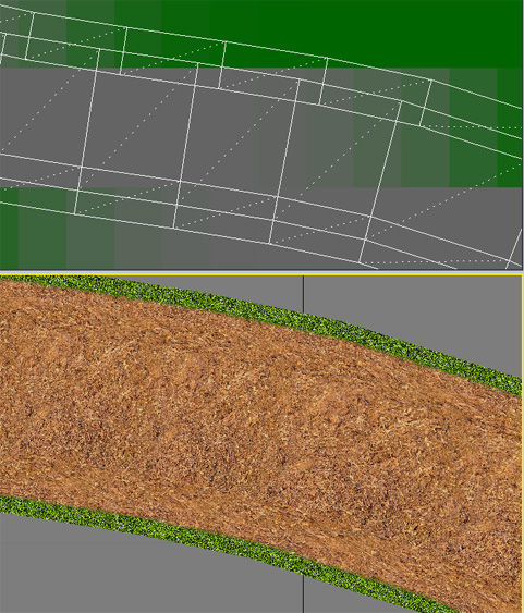
To do this assign the texture material in the usual way to the fringe and select the UVW mapping from the modifier. Before the mapping was set to Planer but for a fringe we set it to Face. Tiling is usually left at 1.0
When this is done the result will probably look like the image above.
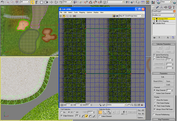
To correct this we simply have to rotate the mapping 90 degrees.
You can do this in the Unwrap UVW modifier by selecting the entire face and using the Rotate mode. After rotating the fringe texture will appear as shown on the left side of the above image. A great looking rough sand fringe.
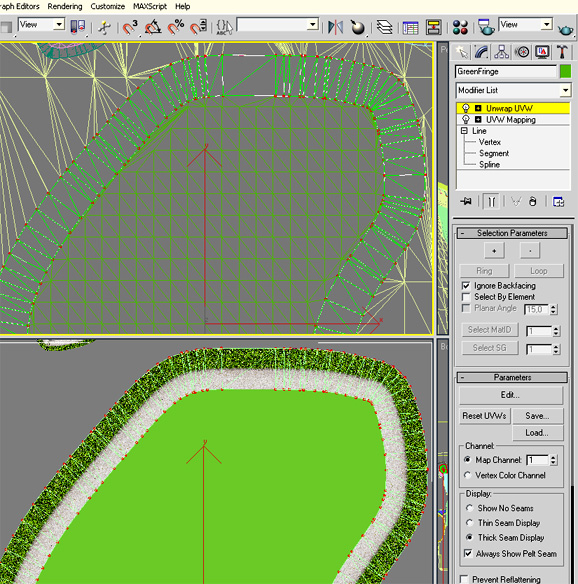
Use the Unwrap and rotate functions for all fringes that have a surface transition
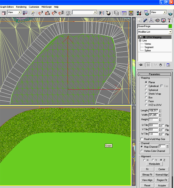
For fringes that don't have a surface transition, only the UVWMapping is required with the U and V tiling settings set to an appropriate value.
Note: Do not remove the backfaces for fringes
Step 11: Creating reflective surfaces
 .
.
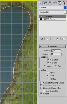
Use the same steps as for creating area surfaces only this time in the Extrude modifier set the Capping option to Morph instead of Grid.
Alternatively, set the capping to Grid as usual and then select the Optimize function from the top menu Modifiers/Mesh Editing list. This way the number of polygons will be kept at a minimum. ( about times times less than the Morph method).
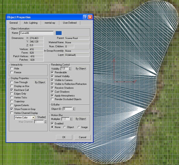
After converting the object to Editable Patch you should see the pond looking something like the above image. If not then open up the Object Properties window (right click on object to access the properties window). When open, switch the Edges Only option off in the Display Properties. This applies to objects when the polygons or grid doesn't show up.
Reflective surfaces can also be assigned a suitable water material. Do this in the usual way.

Here the two ponds have been assigned a water texture material
Reflective surfaces must be identified by the GGS renderer in order to actually reflect.
As with overlapping surfaces you add an identifier to the name of the object that should reflect.
The naming convention is either "Reflect......"). "ReflectPond2", "ReflectStream1" etc ... or just "Pond..." or "Stream..."
That's it. Just repeat all the above operations for all surfaces.
If you just want to create surface overlays to enhance you your existing course hole made with a large main texture map then you are finished. The only thing left is to export the model to a .3ds format. (GGS only reads 3d models in .3ds format).
Step 12. Export the model to .3ds format.
After saving your work in the standard .max format, go to the File/Export menu item. Browse to the GGS Courses folder and select your course folder.
Once again, there is a naming convention so that GGS can detect if the model exists and automatically load it.
If this is a surface overlay then the naming convention is XxSOM*.3ds where Xx is the first two letters of the course name and * is the hole number (0 for driving range), SOM stands for Surface Overlay Mode and -m is dash followed by the model number
eg PrSOM4-2.3ds is for the SOM model 2 on Hole 4 of the ProTee course.
If this a full surface model then the naming convention is XxTerrain*.3ds where Xx is the first two letters of the course name and * is the hole number (0 for driving range). eg PrTerrain4.3ds for the ProTee course Hole 4.
Go to 3dsMax Tutorial Part 5 here
Notes:
You should not re-import the 3ds format model. Make all changes in the original .max file and export again.
When you create a new material, add it to the Library so that when you make the next hole model all the texture materials are already there for you to use.
Make regular backups of your model file. It's easy to delete objects or mess up somehow without noticing it.
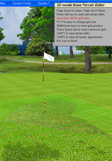
In GGS when using Surface Overlays you may see the underlying surface pop up through the overlay at certain places. This is due to the difference in rendering resolution between the Overlay surface and the underlying terrain. (The surface overlay is usually rendered at a much higher resolution level than the underlying terrain).
You can fix this directly in GGS with a special tool that modifies the underlying terrain height. With the Base Terrain Editor (ctrl/B) you can push the underlying terrain back down. Move the ball to the area before activating the Base Terrain Editor with the (ctrl/B) and use the page down key until the underlying terrain has disappeared.
The inherent problem with using a large single texture map
The inherent problem with using just a large texture map for the complete course hole is that the texture must be stretched across the entire course hole. In so doing, the texture gets fuzzy and lacks detail. Due to the grass structure textures that are rendered over the surfaces the surface detail is enhanced dramatically but the transition between varying surface types is still fuzzy. This is particularly noticeable around bunkers, greens and footpaths. Also, only one grass structure texture can be rendered for the entire scene so that when the camera is near a bunker surrounded by rough the graphics engine must decide to render either a sand structure or a rough structure. There is no way to limit the sand structure to just the sand and the rough structure to just the rough without a 3d model. What actually happens in such a case is that the graphics engine will opt for one or the other depending on how near the camera is to the surface. This then causes either grass structures appearing in the sand or sand structures appearing in the rough. The same goes for greens with either rough surrounding them of sand bunkers near by.
Overlayed Surface Models will eliminate this problem because models can be assigned separate textures individually and these can then be rendered on top of the main texture map.
-
-
 Home
Home Sensors
 Cameras
 Software
 Enclosures
 GSA Courses
 E6 Courses
 Business
 Tech News