![]()
Carry Adjustments
![]()
There are numerous ways to adjust the measured speed of the ball and thus it's carry distance in the GSA Golf Control Panel.
These include:
1. Adjusting the Vcam scaling factor
2. Setting Individual carry factors for each club
3. Adjusting the speed of the ball based on its launch angle.
4. Adding global boost factors
5. Using fatory calibration tables
6. User defined camera calibration
![]()
1. Adjusting the Vcam scaling factor
The measured speed of the ball is directly proportional to length of the ball trace in the Vcam.
Scaling factor
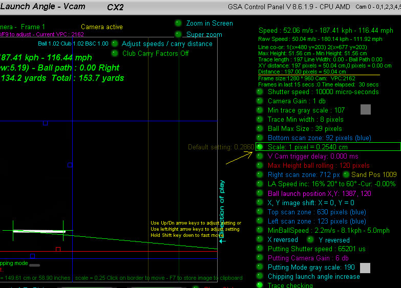
The CP calculates ball speed by the length of the ball trace of the shot.
A ball trace of a fast moving ball is achieved by using relatively long camera exposure times
In the above example the exposure time (or shutter speed) is set to 10000 micro seconds = 0.01 seconds
The length of the trace in the camera image is in pixels so this length (197 px in the above example) has to be converted to real world length units before it can be used in the speed formula v = d/t
This conversion is done by the user defined "Scaling factor"
In the above example the "Scale" is set to 0.2450 which means each pixel in the image is equivalent to 0.2450 cm
In the above the trace length in pixels is 197 which after conversion is 50.04 cm (i.e. 197 x 0.2450 = 50.04)
After this conversion we can use v = d/t = 0.5/0.01 = 50 meters per second
Setting the base scaling factor
Most just use the default setting of 0.2860 but if you would like to be more exact then the following method should be used.
1. Place a length of white tubing or white pole of a known length in the field of view of the Vcam camera
2. Click the Soft Trigger button to grab a new image in the Vcam window
3. Adjust the scale factor so that the "Distance" is the same as the known length of the pole.
In the above example the tube length is 50 cm and the "Scale" is set to 0.2450 so that the "Distance" is also 50 cm
2. Setting Individual carry factors for each club
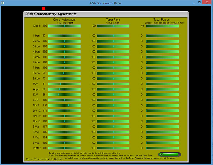
You can also add speed / carry factors for each club separately in this window
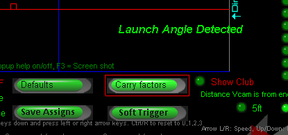
Click the "Carry factors" button in the Vcam window to open the carry facotrs table
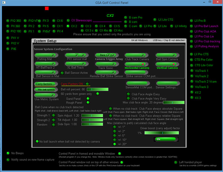
Click the "Carry Factors" button in the CP's Setup window or Vcam window to access the carry factors window.
Note that the "Carry Factors" option has to be set ON in order for them to take effect
There's also a "Driver boost" factor in the Setup window that just adjusts ball speeds for Drivers
Adjust carry and spin directly in the Vcam window
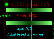
There's a new slider bar in the Vcam window that allows users to adjust the LA based carry and spin factors directly in the Vcam window and thus see the results of carry adjustment immediately.
New speed & spin adjustments based on launch angles as well as club types
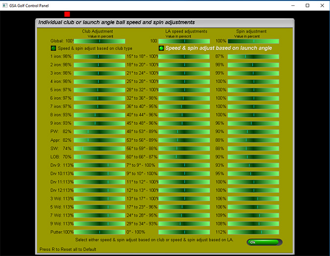
In addition to the carry & spin factors based on the club being used, there is now a carry (ball speed) factor and spin rate factor based on ball launch angles.
This should be more accurate than the club based method as it cannot be what the launch angle is based on the club selection.
Note that these carry and spin factors are either club or LA based and not both together. If "Carry factors" are switched OFF then neither will be used.
The third column in the window is used to set spin rate factors for specific clubs or launch angles. Again, if "Carry factors" are switched OFF then these spin factors will not be used.
Also note that the standard LA speed increase or decrease is still active in the Vcam window when selecting carry factors ON.
Click the above image and scroll down to Q 16 to read more about standard LA speed adjustments.
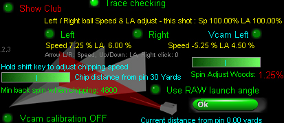
3. Adjusting the speed of the ball based on its launch angle.
"Launch angle ball speed adjustments"
In addition to ball speed adjustments for balls flying left or right, there's also ball speed adjustments related to the launch angle of the ball.
The reason for this is because as the ball flies higher with higher launch angles,
the ball is getting further away from the floor mounted camera and thus the trace length appears smaller
which in turn results in lower speed measurements.
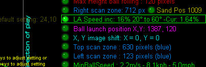
To correct this an "LA Speed" adjustment based on the launch angle of the ball can be set.
In the above example, a max ball speed increase of 16% is set over an LA range of 20 to 60 degrees.
This means that if the ball LA is below 20 degrees then no adjustment will be made but if higher then a percentage of the 16% will be applied to the ball speed.
e.g. If the LA is 60 degrees then the full 16% will applied, if 40 degrees (i.e. halfway between 20 and 60 degrees) then there will only be an 8% (half of 16%) increase.
(BTW the "Cur:" means Current percentage increment used based on the current launch angle of a shot)
Note that if not using this adjustment, high lofted shots may carry too short while woods and long iron carry distances are OK
Also note that this adjustment can be reversed. i.e. the percentage adjustment can be minus and thus the ball speed will be decremented instead of increased with increasing launch angles
Launch angle adjustments (only used when calibration is OFF)
All the calibration work done recently has shown that un-calibrated measured launch angles are far lower than what they really are as viewed by the cameras. Usually around 25 to 30% less
For those that prefer linear adjustments over calibration we've added a linear launch angle adjustment in the Vcam window in this version of the CP
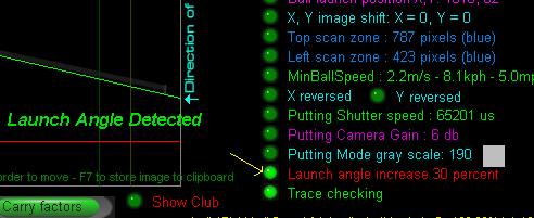
Just click multiple times on the new "Launch angle increase" option to set the LA increment to be 0, 5, 10, 15, 20,25, 30 or 40%
4. Adding global boost factors
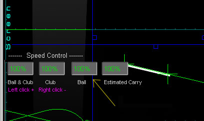
Switch the "Adjust speeds / carry distances" ON to display the global speed controls.
The default setting is 100 %. Increasing or decreasing the "Ball" speed control will increase or decrease all measured balls speeds for all clubs.
Other adjustments
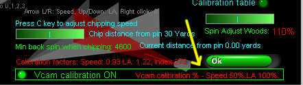
Chip speed
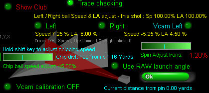
Even though the CP measures correct ball speed when chipping, these shots are often too long in the game software.
i.e. the ball travels too far and skips off the green to the other side
To correct this, you can set a ball speed adjustment percentage to reduce the speed of the ball.
In the above example, the speed of the ball when chipping is reduced to 45.00% of the actual measured ball speed.
This speed adjustment will only kick in when the system is in chipping mode and chipping mode will only kick in when the ball is not on the green
but the distance the ball is to the pin is less than the user defined chip distance.
Chip distance
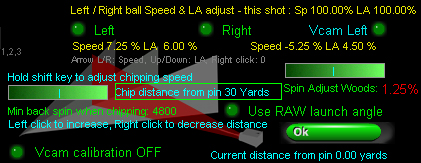
To set the chip distance, hover the mouse cursor over the "Chip distance from pin" text and use left and right mouse clicks adjust the distance.
In the above example the distance to the pin where the chipping mode will be automatically activated is set to 30 yards.
"Min back spin when chipping"
Another major factor when chipping is the measured or calculated back spin
In order to prevent the ball from rolling straight off the green when chipping, the back spin should be quite high.
Use the slider bar to set the "Min back spin when chipping" to at least 4000 rpm
"Spin rate adjustments"
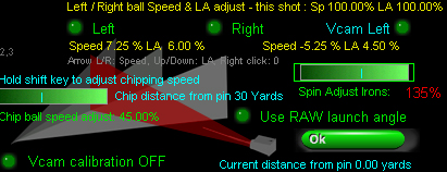
When not using our ball spin cameras, spin rates are calculated from club and ball launch data
Use the spin adjust slider bar to increase or decrease the calculated spin rates.
In the above example, calculated spin rate for all irons has been increased by 135%
Note that spin rate adjustment settings are separate for irons and woods. Hold the shift key down to select irons, otherwise woods are selected.
Hcam path correction
Some small tweeks were made to the Hcam path correction today and the new 7ft calibration table was made with Hcam correction ON.
5ft and 6ft tables didn't use the Hcam correction so will be redone mext week. In the meantime use the 7ft table even if your Vcam is closer or further away.
Chipping mode
When in Chipping Mode, the "min backspin when chipping" slider bar turns into .... "chip ball speed adjust"
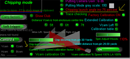
and "Launch Angle inc" turns into "Chipping launch angle inc"
Note "Launch Angle inc" is not required when using "Extended Calibration".
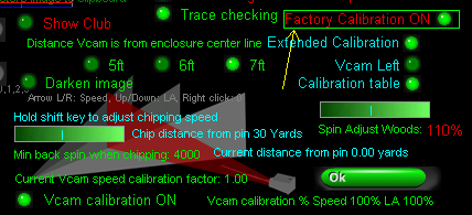
5. Factory calibration table set
All current GSA Golf Control Panel versions and updates now include a factory set camera calibration table
that negates any user requirement to calibrate the cameras themselves.
The table consists of 3 calibration tables each consisting of 126 entries
for various distances the Vcam is from the center line
Vcam distances from the center line are 5ft, 6ft and 7ft.
Note that the calibration table "calibLRex.csv" is placed in the "C:\Program Files (x86)\GSAControlPanel\data" folder when you download the latest CP update.
In order to use it, the new "Factory Calibration" option must be on.
Any user calibration tables won't be overwritten when this option is on but if you would like to edit the factory tables then switch the "Factory Calibration" option OFF again before editing.
The table will then be automatically saved to the "C:Users\Public" folder.
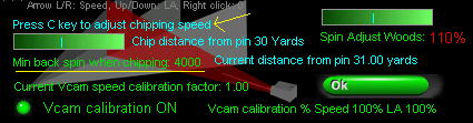
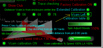
Calibration factors used now displayed
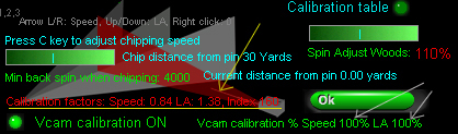
The calibration factors used for the current shot are now displayed in the Vcam window.
These are Speed adjustment, Launch Angle (LA) adjustment and the index number into the calibration table.
In the above example, the raw speed of the ball was reduced to 84% and the raw LA increased by 38%
Extended calibration "Scale" factor = 0.2780
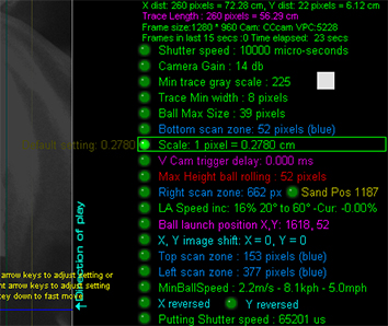
Note that the Scale factor for the calibration tables was set to 1 pixel = 0.2780.
This scale factor used with the calibration tables should result in exact ball speed measurements across the entire 0 - 60 degree launch angle and +/- 20 degree path range.
Increasing or decreasing this scale will result in decreased or increased measured ball speed across the entire range should you care to change it.
Don't forget !
If your Vcam is mounted on the left side of the enclosure, ensure that the "Vcam Left" option is ON
otherwise your calibration will be reversed
Also don't forget to set the distance your Vcam is from the enclosure center line
Currently distances are 5ft, 6ft and 7 ft.
If your Vcam is over 7 ft away from the center line then just use 7ft setting for now.
Other distances will be available later this year
Also don't forget to set the amount of calibration to 100% for both speed and LA to start with
Later you can reduce or increase the amount of clibration for both Speed and LA to suit
In the above example the speed calibration was reduced to 50% so that any ball speed adjustments for ball hit left or right will be 50% less
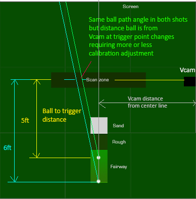
Note that the calibration tables where made with a ball to trigger distance of 5ft.
Later next month we'll have exact speed calibration percentages for various other ball to trigger distances
Also don't forget to set "Extended Calibration" ON and "Factory calibration" ON
6. User defined camera calibration

Click the above button to read about user defined calibration
Notes
Before adjusting the scaling factors, check the below described possible issues and factory calibration settings
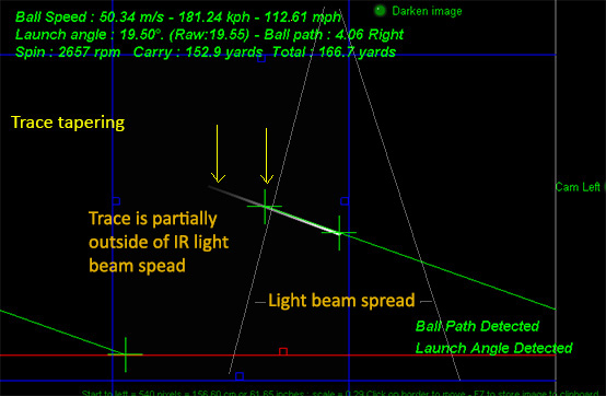
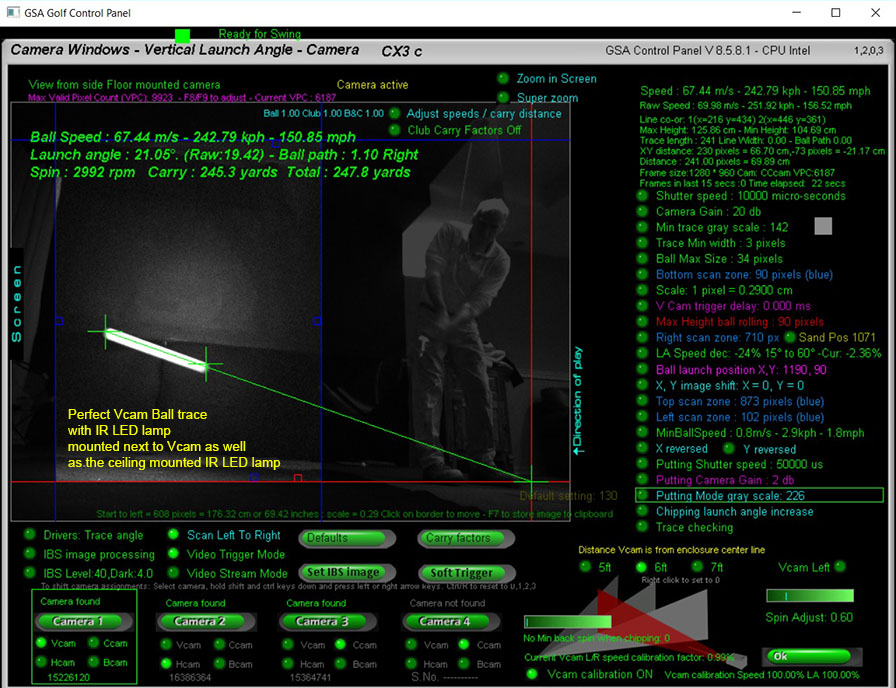
As measured ball speed is directly proportional to the length of the ball image trace , it's important that the ball trace from beginning to end is well illuminated.
With really fast high speed shots, it is possible that the ball won't be sufficiently illuminated to leave a solid trace and appears to taper out towards the end.
The image processing software in this case won't detect the full length of the trace and thus the measured ball speed will be too slow.
In order to avoid this problem you either need to tilt the IR Lamp further towards the screen
or additional illumination (either IR LED or Halogen) has to be added further ahead towards the screen.
In addition, an IR LED lamp should be mounted next to the Vam so that the ball is also illuminated from the side.
The side mounted Vcam IR lamp should be tilted upwards around 18 degrees
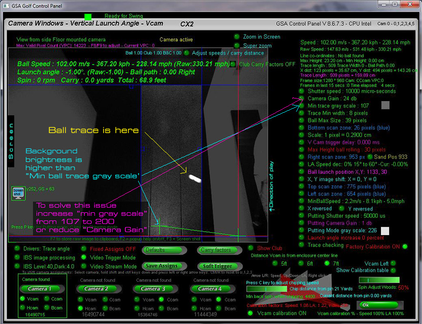
Customer "Ken" sent us this Vcam image after a shot.
Notice that the bright ball trace is not being picked because the background is too light and the "Min Gray Scale" is set too low.
![]()
![]()

 Home
Home Simulators
 Cameras
 Software
 Enclosures
 GSA Courses
 E6 Courses
 Business
 Tech News