
Please note:
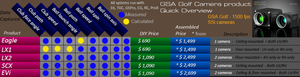
Regular stereo systems are now EOL (End of Life)
and are replaced with the new VisTrak system.
 -
-
Click above image to see the VisTrak systems


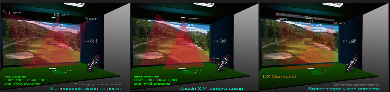
! Note: this setup procedure is only for the CX stereo parallel camera configuration !

Click the above button to read about CX converging camera setups.
 -
-
CX Stereo Calibration
Note that all CX Surround systems are individually pre-calibrated so re-calibrating will not be necessary.
Note: please use Control Panel version 8.7.9.9 or greater for this procedure.
Calibration procedure
Should re-calibration be required then the following calibration procedure should be made:
Calibration setup
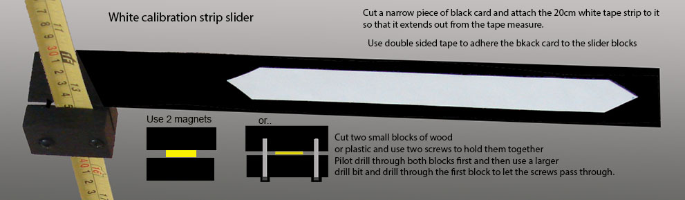
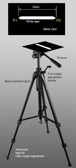
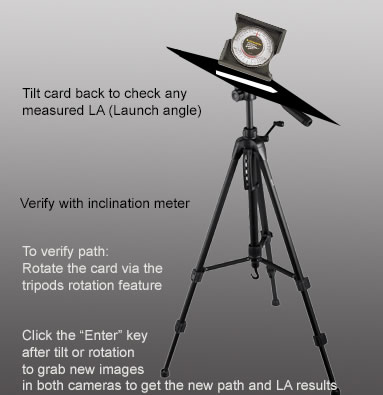
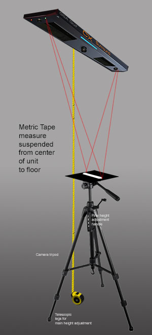
In order to calibrate, we need to raise a 20cm white strip mounted on a black card from the floor up to the cameras in 10cm steps.
A metric tape measure is suspended from the center of camera casing and extended to the floor.
The above images show two methods of raising the height of the calibration strip.
i.e. you can either use a camera tripod and lab stand or
attach the white strip card directly to the tape measure and simply slide the strip up or down..
Note that calibration table consists of 12 to 30 row entries at set 10cm distances from 300cm to 0cm.
i.e. 300, 290, 280, 270... to 0 cm
If your camera height is not exactly at a 10cm interval (i.e. 283 cm instead of 280cm or 290cm) then a extra entry adjustment will be required later
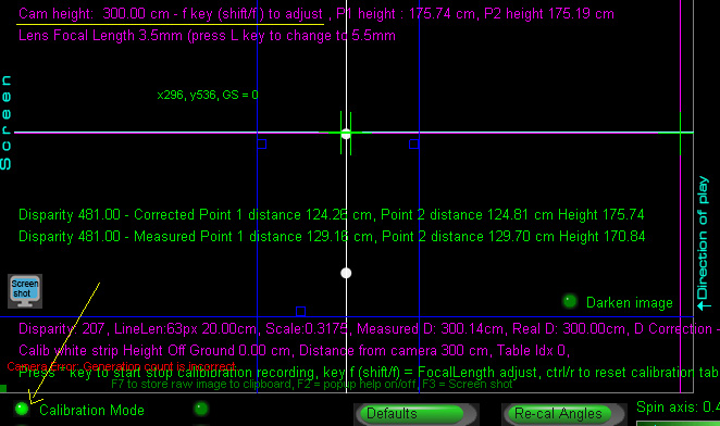
The Control Panel is set into calibration mode and the height the unit is mounted from the floor is entered into the system using the f and shift/f keys.
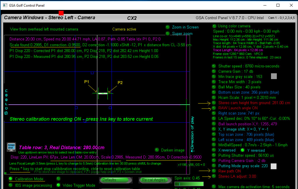
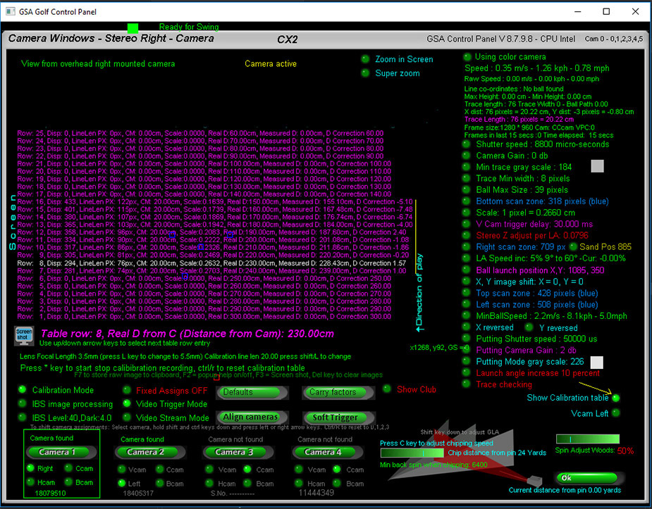
- The above image shows the Control Panel in stereo camera "Calibration mode" in camera 2.
- Note that there is a measured distance from the camera "Measured D" , a real distance "Real D" and a correction
- value "D Correction".
- The calibration table consists of scaling and height (or distance from camera) values.
- The scaling factor is the factor used to convert distances the ball travels left, right and forward in image pixels to real
- world distances in cm.
- The "D correction" value corrects the measured distance the ball is from the cameras to the real distances.
- In the above example, the measured distance the ball is from the camera was 280.95 cm while the real distance was 280.00.
- The correction value is calculated by subtracting the measured distance from the real distance (280.95 - 280.00 = 0.95)
- Applying the correction value to the measured value corrects the distance discrepancy
- There is a correction value in the table for every 10 cm in height (or distance)
- and these correction values are weighted for all ball height distances that lie between the 10 cm steps.
- i.e. a measured distance of 275 cm will have a correction value between the values for 280cm and 270cm.
- Before starting, ensure that the calibration line length has been set correctly in the Control Panel
- There's a choice of either 20cm or 30cm.
- The above image shows the calibration line len to be 30cm.
- Most will probably use a 20cm line len strip. Use the key shift/L to change from 30cm to 20cm
- or vice versa if using a 30cm white strip length.
12 Calibration steps
- To start the calibration entry process, press the * key.
- This allows you to make entries into the calibration table.
- Using the up down keyboard arrow keys (ensure that no other parameter setting is active)
- select the table entry to the nearest "Real D" ( Real Distance) above the camera height value.
- i.e. if the camera height is set to 283cm then select the 290 cm "Real D"
- Step 1: Place the card at the floor level directly under the CX Surrounds center point
- i.e. between the two cameras.
- Ensure that the white strip on the card is pointing directly forward
- Step 2: The user triggers both cameras (by pressing the Enter key) to capture images from both cameras
- so that a basic height, a disparity value, a height correction and a scaling factor for the known length of the tube
- is calculated.
- Note that the white tape strip represents a ball trace with 2 3D points at either end of the strip
- so ensure that system detects both ends of the tape strip in both cameras.
- Check both camera frames with every step to verify that both ends of the white strip are detected
- as it is quite possible that the tape measure or parts of the tripod may be being picked up inadvertently.
- Use the blue border lines to confine the valid FOV so that only the white strip is detected.
- Step 3. The user preses the "Ins" key to store the values.
- --
- Step 4. Now move the card up to the first or next 10 cm marking on the tape - using either the camera tripod or lab stand -
- and select the next row height step (arrow up key) in the calibration table.
- i.e. if you started at Real D 280cm (Row 3) then select 270cm (Row 4 and move the card to the 270cm marking
- on the tape measure
- Step 5: The user repeats these steps 12 or so times for a total height of 120 cm or as high as possible before
- the card's tape strip goes out of the FOV of the cameras..
- When raising the black card with white strip on it, make sure to keep the card and strip level.
- With every step, ensure that both ends of the white strip on the card are detected in both cameras
- (i.e. the green cross hairs are exactly at both ends of the white strip in cameras 1 and 2)
- Also ensure that the tape measure or any part of the Tripod or Lab Stand is not being picked up.
- Either use the blue valid FOV borders block these out of the valid FOV of the cameras or cover the stands with a black material.
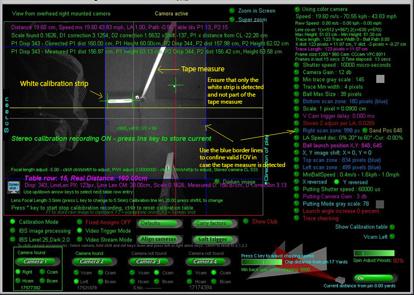
The above image shows the white strip connected to the tape measure with the slider.
Using the calibration slider on the tape measure, a complete calibration can be done in 10 to 15 minutes.
When testing, set both RAW Path and RAW Launch angle to ON
You can view the complete calibration table by selecting the "Show calibration table" option.
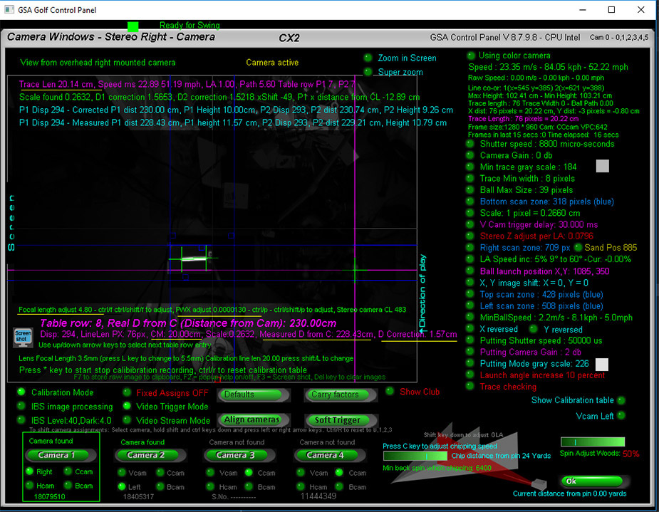
Focal Length and Pixel Width (PWX) adjustments
Focal Length and Pixel Width adjustments should be set to values that reduce distance measurement corrections to a minimum.
In the above image ( taken in the office here) show that the distance correction for the calibration strip is 1.57 cm.
i.e. as the measured distance the strip is from the camera is 228.43 cm when its real distance is 230cm,
a 1.57cm correction value is required to correct the 228.43 cm to 230.cm.
- The above calibration table shows 10 set entries for real distances the strip (or ball) is from the camera from 240cm to 150cm
- Correction values are from 1 cm to -5.10 cm for the distance range.
- All other entries (300 cm to 250 cm and 140cm to 60cm ) have not yet been set.
- Before starting the calibration process, set the calibration strip to floor level and take a reading.
- i.e. hit the Enter key to grab new images in both cameras.
- Using the up / down keyboard arrow keys, select the table row for this floor distance (240cm in the above image case)
- and - while in calibration entry mode - hit the "Ins" keyboard key to
- Reminder: To start the calibration entry process, press the * key.
- If you see that the distance correction value is greater than 1 or 2 (i.e. in the 10 to 60 range), then adjust the PWX value (using the Ctrl/P and Shift/Ctrl/P keyboard keys)
- until the correction is in the 1 to 2 cm range. The above images show the PWX value to be 0.0000130 and yours will probably be similar:
- Focal Length adjustments will also help but mostly it should be left in the 3.5 to 5mm range.
- Note: please use Control Panel version 8.7.9.9 or greater for this procedure.
CX Surround Accuracy
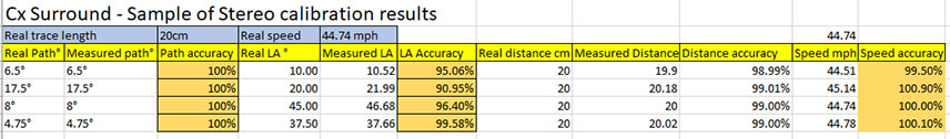
The above test results table sample shows near perfect path and ball speed accuracy.
Launch Angle - as May 2018 - still requires tweaking a bit but still very good.
We doubt that any of our competitors can beat these figures. Not that anyone could confirm their claims to this degree of accuracy anyway.
Lens focal length
Note that standard H and V cams use lenses with a focal length of 3.5mm so ensure that the 3.5mm focal length is selected as in the above image
Note: Some CX Surrounds will be using 5.5mm lenses.
The advantage of the 3.5mm lenses is that they have a greater FOV range.
Virtual checker board
Instead of using a large cumbersome checker board to calibrate the stereo cameras,
this method uses a virtual checker board that automatically scales and positions itself depending on the position and image size of the white tube
Note that the CX Surround uses super low distortion lenses so lens bend doesn't have to be taken into account
- Note that even though the calibration is only made in 10cm steps, the calibration
- values are weighted for every ball position in 1 cm steps in 3D space.
- Example:
- The real ball height off the ground is say 105 cm with a stereo camera disparity value of 296
- The calibration table has height correction factor values of 0.28 & 0.14 for 100 cm and
- 110 cm based on the disparities 290 & 302.
- The disparity percentage difference is then 296 / (290 + 302) = 0.5.
- So the real height correction is actually halfway between 0.28 and 0.14
- i.e. 0.28 + 0.14 x 0.5 = 0.21
- Tests with a laser distance measurement instrument confirm that the weighted correction value
- is well within the 1cm tolerance.
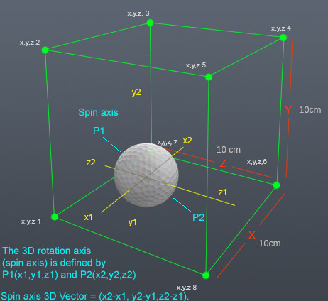
- Disparity
- Disparity ( the offset between 2 points in 2 images from 2 cameras) is used to calculate the
- distance the point or object is away from the camera.
- It is used in the formula D = bf / d
- where D = Distance of point in real world = (base offset) * (focal length of camera) / (disparity)
- Scaling factors
- The calibration table also consists of a scaling factor for each height.
- It is calculated by taking the real length of the white tube (a constant 20cm) and dividing it by the
- length of the tube measured in pixels
- (which - of course - varies depending on the distance the tube or object is away from the camera)
- The scaling factor is used to measure the distance the ball deviates from the center line left and right (ball path)
- and the distance the ball has traveled forward.
- Scaling factors convert distances measured in pixels to real world distances measured in cm or inches.
- CX Surround - Raw path and LA vs Fixed point path and LA.
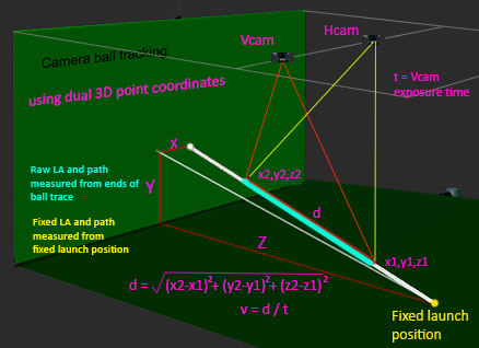
Although the real distance (d) the ball travels (and thus the ball speed) within the camera exposure time is always measured using RAW LA and Path
(i.e. as measured from the both ends of the ball trace)
it will be more accurate to measure LA and path using fixed launch positions for chipping as by the time the ball is in the FOV of the cameras with slow shots
the ball may well be descending and thus launch angles will be less or even negative if measured from trace ends instead of a known launch position height.
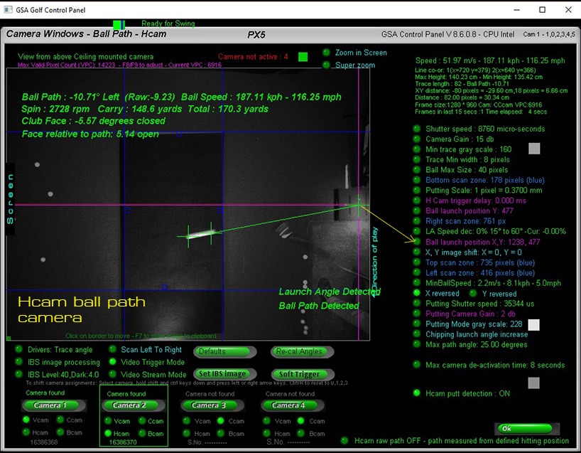
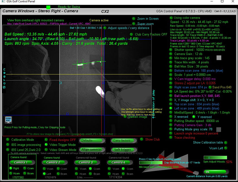
Note that when using a fixed launch position (i.e. when both the RAW LA and RAW path options are switched off)
then the fixed "Ball launch position" has to be set in both the left and right cameras separately
as the left and right cameras will see the launch position in a different places.
Switch RAW Path and RAW LA on/off in camera 2 of the Control Panel
Calibration fine adjustments
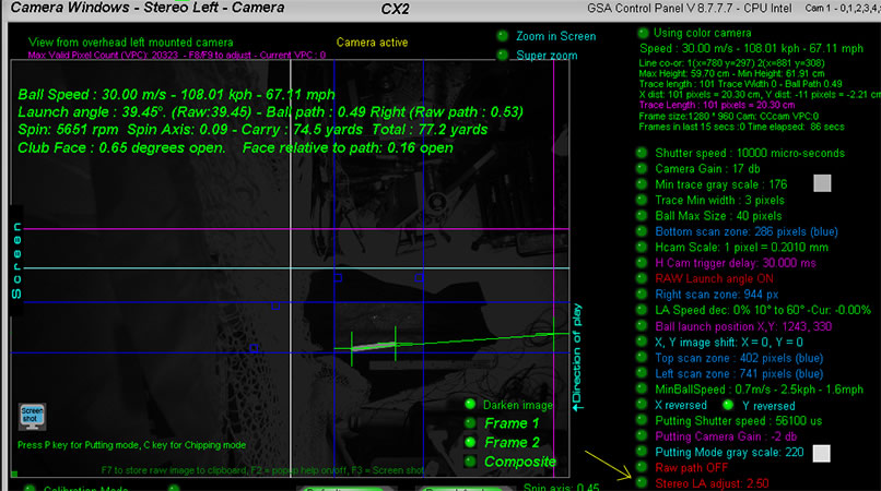
Use the Stereo "LA adjust" to fine adjust launch angles (visible in Camera 2)
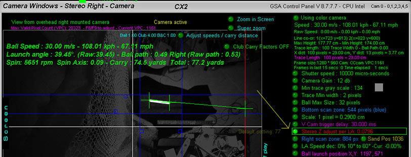
Use the Stereo "Z adjust LA" to fine adjust the measured Z distance depending on launch angle (visible in Camera 1)
Z distance is the distance the ball traveled forward without vertical launch angle and it directly
effects the actual distance the ball has traveled and thus the measured ball speed.
Use this feature if you find the measured ball speed is decreasing slightly with increasing LA.
Note: You will probably only notice this during the calibration tests when using the calibration card and strip to simulate a ball trace.
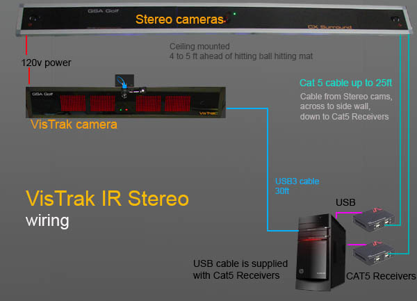
Setting up the V and H cams to a stereoscopic system
- If setting up the V and H cams to a stereoscopic system, mount both cameras with their mounts either
- on a wood board (3ft x 1" x 3" will suffice) or directly to the ceiling 60cm (23.6") apart facing straight down.
- Mount the board (or cameras) on the ceiling so that center of the board (or cameras) is exactly over the center line of the enclosure
- (best to use a plumb line for this)
- and the cameras are spaced 30cm apart from the center line, left and right.
- In order to ensure that the cameras are facing straight down some adjustment may be required.
- To adjust, place two golf balls 30cm apart from the center line directly under the cameras
- (use a plumb line suspended from the base of the camera) and another two
- golf balls a few feet ahead or behind of the other two balls.
- Switch to video stream mode in the V and H cams and align the cameras on their mounts so that the horizontal and vertical center lines of the
- camera image are exactly over the appropriate balls.
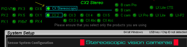
Select the "Stereoscopic" option in the CP's setup window (top center) and select CX2 mode. (we haven't tested with club tracking yet).
Go to the Vcam window and select "Calibration Mode" and use th f and shift/ f keys to set the camera height value to match your actual camera height from the ground.
Exit the Calibration mode.
Notes: As high lofted flying balls cannot be nearer than 70 cm to the cameras because they will then be out of the FOV, the cameras may have to be moved further towards the player (probably 2 or 3ft or so from the hitting position)
Ensure that both V and Hcams (i.e. left and right cams) have the same exposure time so that ball trace lengths are the same in both cameras.
When testing, ensure that both ends of the ball traces are being detected in both cameras.
Pros and Cons of Stereoscopic vs H cam V cam setups
- Stereoscopic Pros
- 1. Increased ball speed detection accuracy
- Unless calibrated correctly , the V an H cam setup is prone to ball speed measurement errors and inconsistencies when
- balls are hit left or right and at varying launch angles
- With the stereoscopic setup, measured ball speed is consistent and accurate no matter in what direction the ball is
- going in (left or right) and at what launch angle.
- Note that V and H cam calibration is quite a long and involved process compared to the simple 12 or so step stereo calibration process.
- 2. Both cameras and lighting are mounted out of the way on the ceiling
- The V and H cam setups have additional lighting and a camera mounted at floor level which can be inconvenient
- 3. No light ghosting issues
- With the stereoscopic setup the lighting is not in view of the cameras so there are no light ghosting issues.
- Whereas lighting in the V an H cam setup is both on the floor and ceiling - as are the cameras - and thus ghosting light can get into the camera lenses
- and cause big problems with the image processing
- 4. No calibration required with the CX Surround
- The cameras in the CX Surround are mounted in a fixed locked position and are pre-calibrated before shipping.
- In contrast, the classic V and H cam setups may require a complex calibration to be performed.
- 5. Increased system stability
- As the cameras in the CX Surround are locked and fixed and are ceiling mounted out of the way, there is no danger of the cameras being inadvertantly moved which rerquires resetting the cameras valid FOV.
- Stereoscopic Cons
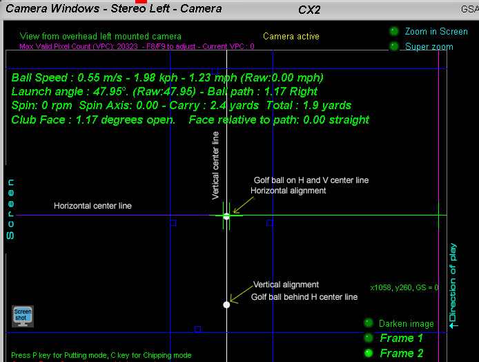
- 1. Camera images of the ball make no sense to the viewer
- Unlike the V and H cam setups where the user can easily see the launch angle and path of the ball,
- the ball images in a stereoscopic system show no direct relationship to LA and path to the average user.
- See "CX Surround Test images" below for more info on this.
- 2. Low reflective carpeting maybe required in the FOV of the cameras
- Regular grass turf carpeting does not always produce enough contrast between the ball and the underlying surface in order to detect the ball traces
- See "CX Surround Test images" below for more info on this.
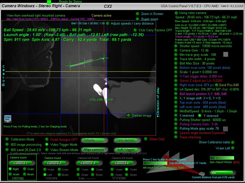
CX Surround Test Images
A small ship on regular turf carpeting showing a nice bright ball trace.
A faster shot on regular turf carpeting
The ball trace is getting very faint and there's barley enough contrast between the ball and the underlying surface for the system to detect the trace..
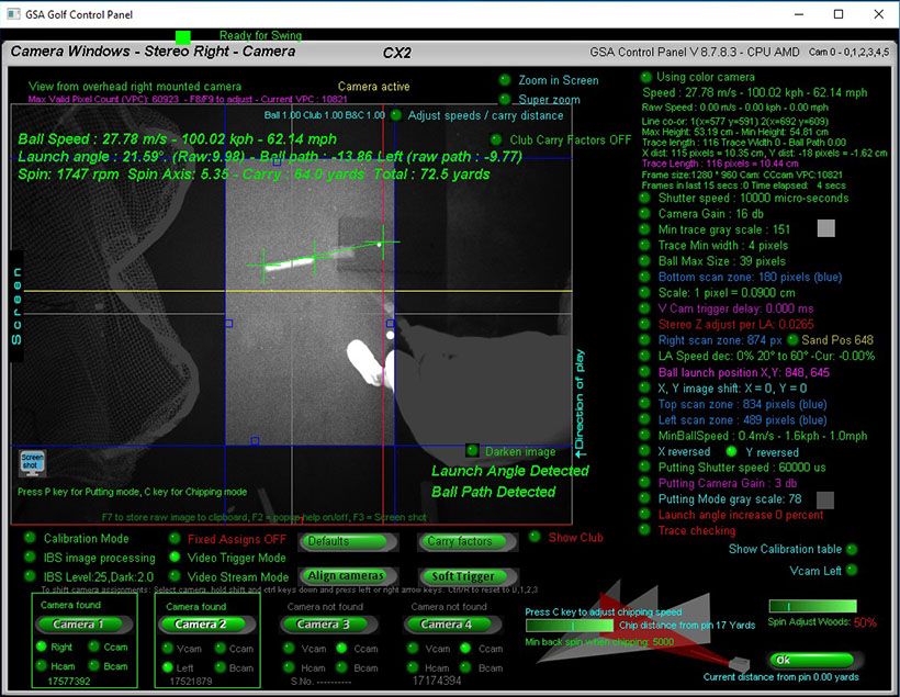
Increasing the camera gain helps but this shot was just 62 mph.
At 162 mph the ball trace will be too faint to be detected using regular turf carpeting.
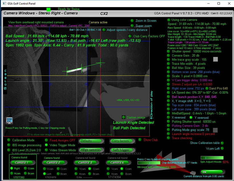
Temporarily laying down some low reflective black carpeting allowed the camera gain to be further increased resulting in a bright ball trace and better contrast.

IBS will probably help with low contrast ball traces though.
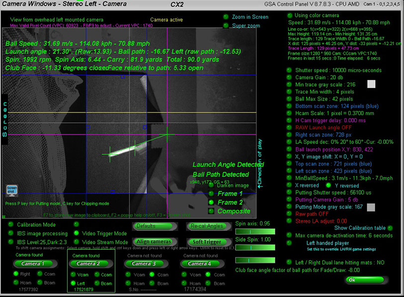
Here's the left camera image of the same shot.
Note that - when comparing the two stereo left and right camera images of a shot - it is not possible to determine
the launch angle of the ball just by looking at the images
whereas in the H and V cam setups it is easy.
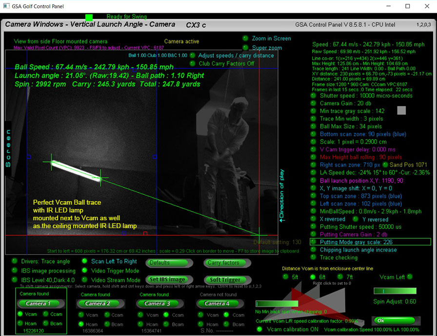
The side mounted Vcam detects vertical launch angle and speed of the ball
The ceiling mounted Hcam camera detects ball path for normal shots
GSA Golf reseller inquiries welcome

Contact Martin for details

 Home
Home Sensors
 Cameras
 Software
 Enclosures
 GSA Courses
 E6 Courses
 Business
 Tech News